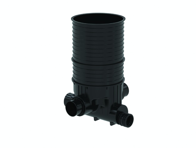
Prince Corfit Inspection Chamber is a robust polyethylene inspection chamber designed to provide convenient access to underground drainage and sewerage networks. Manufactured in accordance with EN 13598-1, it offers a durable, leak-resistant solution for inspection, maintenance and cleaning activities across residential, commercial and infrastructure projects.
Built as a single-piece moulded chamber, Corfit combines strength, chemical resistance and ease of installation. Its lightweight construction, anti-float design and smooth flow characteristics help ensure reliable long-term performance while reducing maintenance requirements throughout the life of the drainage system.
Even the best-designed drainage systems need to be checked from time to time. Since the pipelines are buried underground, inspection chambers provide a practical way to access the network whenever cleaning, maintenance or troubleshooting is required. This makes it easier to deal with blockages and carry out repairs without unnecessary digging.
Inspection chambers provide easy access to underground drainage lines whenever maintenance is required. This makes it simpler to locate and clear blockages, carry out repairs and keep the drainage system operating efficiently over time.

Single piece structure for easy installation and leak-free joints

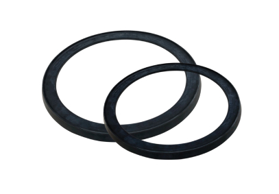
Socket, spigot and side inlet connections with rubber sealing ring

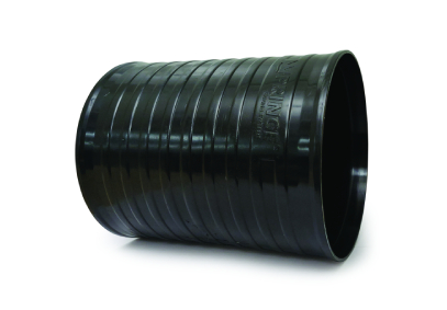
Resistant to floating due to ribs and collar provided on external surface of riser/shaft

Abrasion resistant

Smooth inside invert surface for high hydraulic capacity

Chemical resistant

About 2° slope provided for gravity flow in Inspection Chamber base

Light weight
Inspection Chambers are available in sizes 315mm & 600mm and suitable for invert depth.

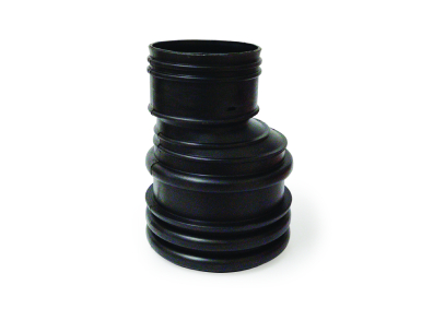
315mm Inspection Chamber

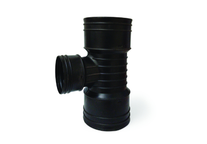
600mm Inspection Chamber with closed side inlets

600mm Inspection Chamber with open side inlets
Note: Open & closed side inlet is available in 600mm. As per site requirement, the required size and side to be cut before installation.


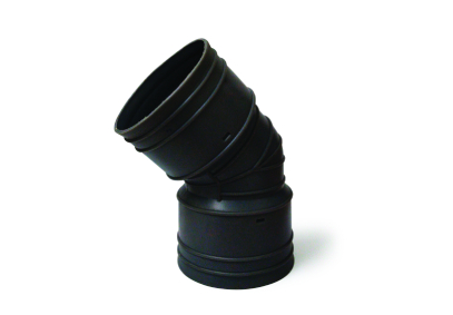
LH & RH - 45° INLETS

RH - 45° INLET

LH - 45° INLET

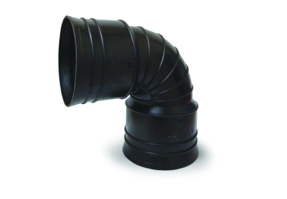
LH & RH - 90° INLETS

RH - 90° INLET

LH - 90° INLET

STRAIGHT
The base of Corfit Inspection Chamber is compatible with below underground drainage pipes:
| Size of Inspection Chamber | Drainfit Pipes as per IS 15328 | Foamfit Pipes as per IS 16098 - Part 1 | Corfit Pipes as per IS 16098 - Part 2 |
|---|---|---|---|
| 600mm Base | 110mm | 110mm | 100mm |
| 160mm | 160mm | 150mm | |
| 200mm | 200mm | 200mm | |
| 315mm Base | 110mm* | 110mm* | 100mm |
It is also compatible with other underground drainage pipes available in the market as per the above mentioned standards.
Note: *For the marked sizes, adaptors will be provided.
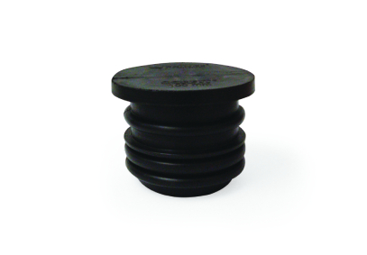
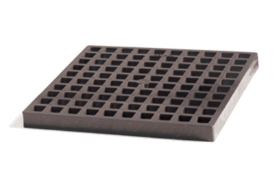
Corfit Inspection Chambers can be equipped with Durafit Chamber Covers on top of the concrete fulcrum ring. These covers are made as per BS EN 124 standards:
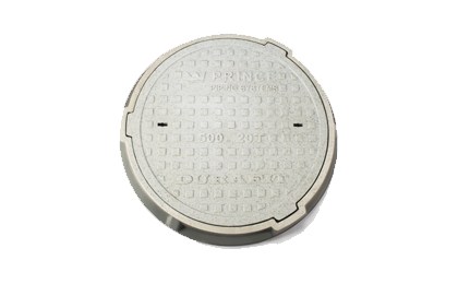
Durafit Chamber Cover
Corfit Inspection Chambers are typically installed at strategic points within underground drainage networks, including:
Correct placement helps simplify maintenance activities while improving the long-term performance of the drainage system.
Corfit Inspection Chambers are compatible with a range of Prince underground drainage systems, making it easier to design and build complete drainage networks using products that work together seamlessly.
| Compatible System | Standard |
|---|---|
| Drainfit Underground Drainage Pipes | IS 15328 |
| Foamfit Structured Wall Pipes | IS 16098-1 |
| Corfit Structured Wall Pipes | IS 16098-2 |
This compatibility provides greater flexibility when designing drainage and sewerage networks across residential, commercial and infrastructure projects.
Corfit Inspection Chambers can be used with Prince Durafit drainage chamber covers that comply with BS EN 124 load classifications.
| Load Class | Typical Application |
|---|---|
| A15 | Pedestrian areas |
| B125 | Footpaths and parking areas |
| C250 | Kerbside applications |
| D400 | Roads and heavy traffic areas |
Selecting the appropriate load class helps ensure safe and reliable performance under site-specific loading conditions.
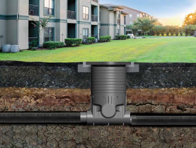
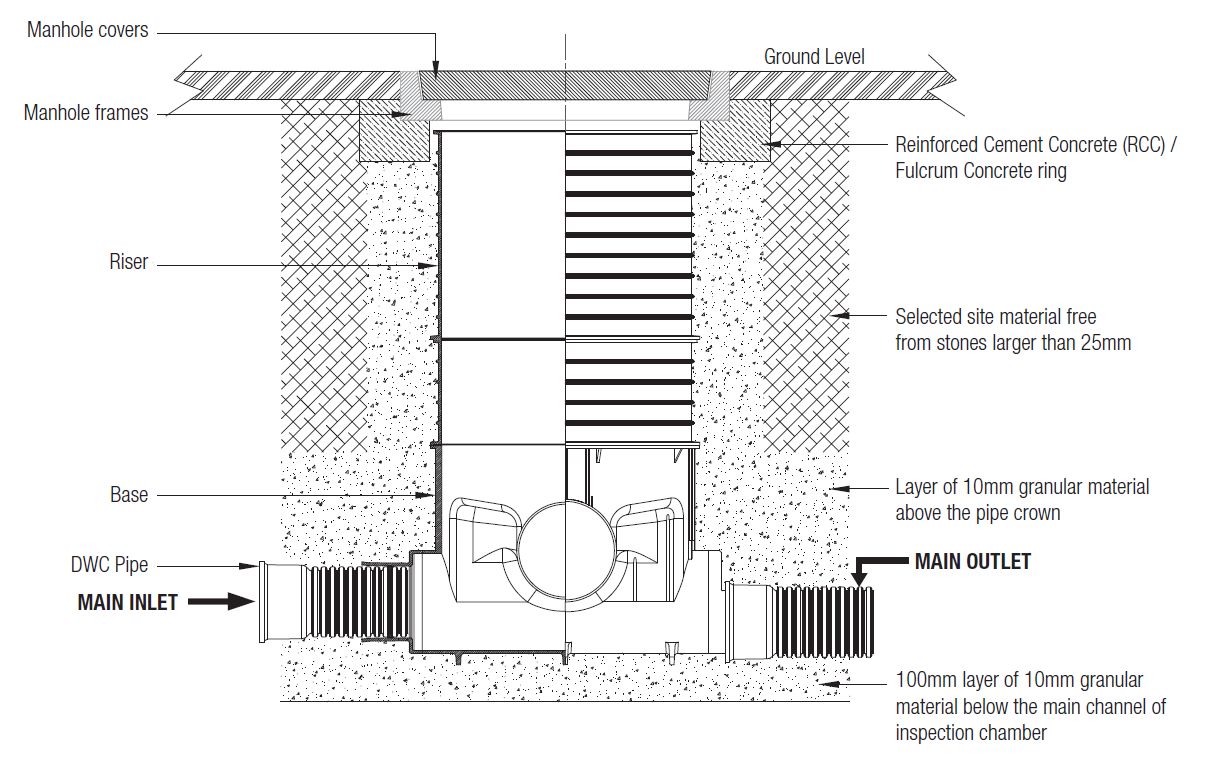
This illustration shows how a Corfit Inspection Chamber is typically installed within an underground drainage network, giving a clear view of how the chamber, riser, cover and connecting pipes fit together as part of the overall system.
Get project pricing, technical support, and BOQ assistance from Prince Pipes